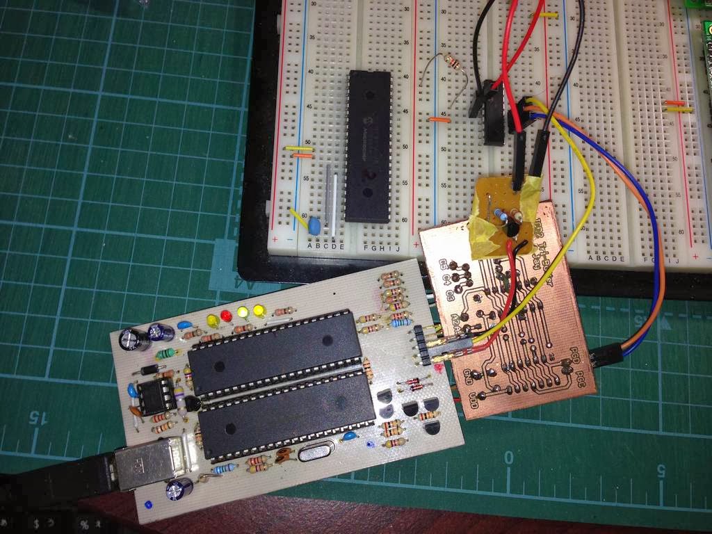
I know Microchip ICD2 is obsolete and we can buy a ICD3 at less than $200 now. BTW, I needed to debug my code on 16F1827 and most of parts were on hand, I had decided to build a ICD2 clone and a Vpp limitter. It took a few days from etching PCB to soldering, now it works fine with old PICs like 16F877A. The thing I added to the original of potyo REV.B. 1) Add SMT 0.1uF caps between VCC & GND of 4550/877A 2) Add SMT 0.1uF and 47uF electro between 5V USB line. (This made the circuit very stable. Before adding these two caps, USB-LED became off when I touch 4550) 3) Add 10K to MCLR of 4550. (no changes) Before working, I did several test as followings; 1) Removed 4550, then jumper the 36pin of 4550 to VCC, and measured the voltage of MCLR of 877A. (reset of 877a) It was 0.1V, so the reset from 4550 should work. 2) Made a small test program for 877A. This program blinks leds (BUSY and ERROR that connected to 877A), so I can see 877A have correct voltage line &...